
Truss bridges are a popular and attractive bridge option for long clear spans for roadways and trails in any situation that requires a bridge. Depending on the material used, typical pedestrian truss bridges can span a range of 80 to even 250 feet long! The difference between a truss bridge and a beam bridge is its triangular shapes which help to support more weight on the bridge.
Learning how to design a truss bridge takes time and a detailed understanding of engineering principles. This article helps to provide a sense of basic truss design principles. Please note, this article is intended as a basic orientation and not a structural design guide.
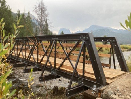
Defining Parts of a Truss Bridge
The first step to designing a truss bridge is to understand and define the main parts of the bridge.
- Truss Frame – This is the outer part of the bridge and includes a top chord, bottom chord, and two end posts.
- Truss Members – The triangular shapes inside the frame that supports the weight of the bridge.
- Foundation/Abutments and Piers – The substructure at the ends of a bridge’s purpose is to support the ends of the bridge to the ground.
- Floor Beams and Outriggers – They provide support for the loads that span between the truss members.
- Decking – This is the surface or floor system of the bridge.
- Stringers – They are the parallel lines of beams over the abutments that support the decking.
Understanding the Basics Behind How to Design a Truss Bridge
Engineers use Newton’s physics when designing a truss bridge. Bridge engineers typically follow the general design process below.
- Using an established structural modeling software, build a wire frame model of the customer’s desired length and width.
- Within the model, apply loads according to set standards (AASHTO or other known loads). Common loads include:
- Live loads (the load from people, vehicles, etc. crossing a bridge)
- Dead loads (the weight of the bridge itself, the decking and deck surface and decorative features)
- Snow and wind loads
- Determine the required strengths for each truss member based on load resistance factor design (LRFD) or allowable stress design (ASD).
- Determine the most optimal member for each element of the truss and the most optimal connection between these elements.
4 Truss Design Options
There are numerous truss bridge designs to select. Here is a brief description of four possible truss designs. Howe and Pratt Truss designs are typically the most efficient, but many others can be used based on aesthetics.
#1 Howe Truss Design
The Howe truss design contains vertical and diagonal members. The diagonal members are in compression, while the vertical members are under tension. The Howe design is the most common design at Areté Structures.

#2 Pratt Truss Design
The Pratt truss design contains angled (diagonal) members under tension and shorter vertical members under compression. Pratt trusses are typically used in Areté Structures’ underslung truss designs. The Underslung truss design is a unique design to Areté Structures pedestrian bridges. All the vertical, horizontal, and diagonal members are placed below the bridge decking.

#3 K Truss Design
The K truss design contains the vertical members in compression. This design “breaks up” the vertical members into smaller sections to reduce the number of elements under tension.
#4 Warren Truss Design
The Warren truss design contains equilateral (or vertical) triangles that help to spread out the bridge’s load. This design alternate compression and tension members and does not contain vertical members.
Get Started on Your Truss Bridge Design
Now that you understand some of the truss bridge designs, allow the Areté Structures team to help move your project forward. Our team will work with you through selecting the bridge’s structure, material, and design.